Advanced AutoCAD 2024: A Problem-Solving Approach, 3D and Advanced, 27th Edition
The Advanced AutoCAD 2024: A Problem Solving Approach, 3D and Advanced book contains detailed explanation of AutoCAD commands and their applications to solve design problems.
Siemens NX 2021 for Designers, 14th Edition
Siemens NX 2021 for Designers is a comprehensive book that introduces the users to feature based 3D parametric solid modeling using the NX software.
AutoCAD 2024: A Problem-Solving Approach, Basic and Intermediate, 30th Edition
AutoCAD 2024 book contains a detailed explanation of AutoCAD commands and their applications to solve drafting and design problems.
Autodesk Inventor Professional 2024 for Designers, 24th Edition
Autodesk Inventor Professional 2024 for Designers is a comprehensive book that introduces the users to Autodesk Inventor 2024, a feature-based 3D parametric solid modeling software.
SOLIDWORKS 2024 for Designers, 22nd Edition
SOLIDWORKS 2024 for Designers book is written to help the readers effectively use the modeling and assembly tools
Solid Edge 2023 for Designers, 20th Edition
Solid Edge 2023 for Designers book introduces the readers to Solid Edge 2023, one of the world's leading parametric solid modeling packages.
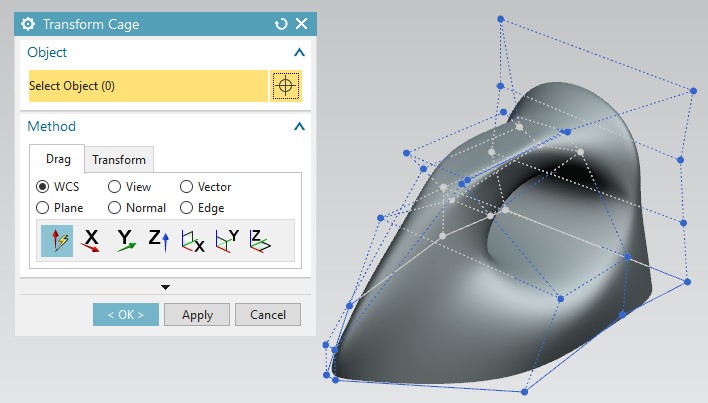
Siemens NX Continuous Release Methodology
Create Iron for product modeling using Realize ShapeTools.
AutoCAD LT 2023 for Designers, 15th Edition
The AutoCAD LT 2022 for Designers, 14th Edition book contains a detailed explanation of AutoCAD LT commands and their applications to solve drafting and design problems.
Thursday, December 19, 2013
Wednesday, December 18, 2013
Friday, December 6, 2013
Monday, November 4, 2013
Friday, September 27, 2013
Wednesday, September 18, 2013
Thursday, September 12, 2013
Thursday, August 29, 2013
Wednesday, August 28, 2013
Monday, August 5, 2013
Introduction to Load Cases in Autodesk Simulation Mechanical
In Autodesk Simulation Mechanical, you can specify multiple load cases for the applied load. This will help you to get the results for multiple load combinations in a single run of analysis. For example, if you want the results for different force magnitudes on a same model than instead of running the analysis separately for all the magnitudes, you can specify multiple load cases in a model that will define the different magnitudes of the force. After defining different load cases, when the analysis is performed, a separate set of results will be displayed for each specified load case in the Result environment of Autodesk Simulation.
Thursday, July 25, 2013
CADCIM Technologies announces the release of Autodesk Inventor 2014 for Designers textbook by Prof. Sham Tickoo
CADCIM Technologies, a pioneer in the field of CAD/CAM/CAE textbooks, announces the release of Autodesk Inventor 2014 for Designers textbook by Prof. Sham Tickoo, Purdue University Calumet, USA and CADCIM Technologies on 2nd Aug, 2013. For detailed information about the textbook and its table of contents, please click on the link given below:
http://www.cadcim.com/ProductDetails.aspx?ISBN=978-1-936646-48-7
CADCIM Technologies announces the release of AutoCAD 2014: A Problem Solving Approach textbook by Prof. Sham Tickoo

CADCIM Technologies, a pioneer in the field of CAD/CAM/CAE textbooks, announces the release of AutoCAD 2014: A Problem Solving Approach textbook by Prof. Sham Tickoo, Purdue University Calumet, USA and CADCIM Technologies on 5th Aug, 2013. For detailed information about the textbook and its table of contents, please click on the link given below:
http://www.cadcim.com/ProductDetails.aspx?ISBN=978-1-936646-55-5
Friday, July 19, 2013
Tuesday, July 9, 2013
Thursday, June 27, 2013
Friday, June 14, 2013
Friday, June 7, 2013
Specifying Multiple Load Cases in Autodesk Simulation Mechanical
In Autodesk Simulation Mechanical, you can specify different or multiple load cases for the applied load. This will help you to get the results for multiple load combinations in a single run of analysis. For example, if you want the results for different force magnitudes on a same model than instead of running the analysis separately for all the magnitudes, you can specify multiple load cases in a model that will define the different magnitudes of the force. After defining different load cases, when the analysis is performed, a separate set of results will be displayed for each specified load case in the Result environment of Autodesk Simulation.
To specify multiple load cases in Autodesk Simulation, choose the Parameters tool from the Model Setup panel of the Setup tab in the Ribbon; the Analysis Parameters dialog box will be displayed, refer to Figure A. In the Analysis Parameters dialog box, by default, the Multipliers tab will be chosen. In this tab, the Load Case Multipliers table is used to add multiple load cases for the applied loads. Note that the rows of this table represents load cases. You can add multiple rows, as required, for representing load cases by using the Add Row button. Figure B shows the Analysis Parameters dialog box with multiple load cases added.

Figure A - Analysis Parameters dialog box

OTHER RELATED POSTS
Applying Remote Force in Autodesk Simulation Mechanical
http://allaboutcadcam.blogspot.in/2013/05/applying-remote-force-in-autodesk.html
Midplane Meshing in Autodesk Simulation Mechanical
http://allaboutcadcam.blogspot.in/2013/05/midplane-meshing-in-autodesk-simulation.html
Applying Frictionless Constraint in Autodesk Simulation Mechanical
http://allaboutcadcam.blogspot.in/2013/04/applying-frictionless-constraint-in.html
Introduction to Effective Mesh in Autodesk Simulation Mechanical
http://allaboutcadcam.blogspot.in/2013/04/introduction-to-effective-mesh-in.html
Variable Pressure in Autodesk Simulation Mechanical
http://allaboutcadcam.blogspot.in/2013/04/variable-pressure-in-autodesk.html
Hydrostatic Pressure in Autodesk Simulation Mechanical
http://allaboutcadcam.blogspot.in/2013/04/hydrostatic-pressure-in-autodesk.html
Remote Load in Autodesk Simulation Mechanical
http://allaboutcadcam.blogspot.in/2013/04/remote-load-in-autodesk-simulation.html