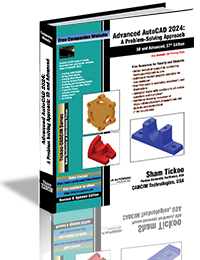
Advanced AutoCAD 2024: A Problem-Solving Approach, 3D and Advanced, 27th Edition

The Advanced AutoCAD 2024: A Problem Solving Approach, 3D and Advanced book contains detailed explanation of AutoCAD commands and their applications to solve design problems.

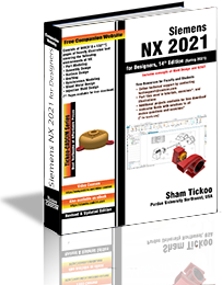
Siemens NX 2021 for Designers, 14th Edition

Siemens NX 2021 for Designers is a comprehensive book that introduces the users to feature based 3D parametric solid modeling using the NX software.

AutoCAD 2024: A Problem-Solving Approach, Basic and Intermediate, 30th Edition

AutoCAD 2024 book contains a detailed explanation of AutoCAD commands and their applications to solve drafting and design problems.

Autodesk Inventor Professional 2024 for Designers, 24th Edition

Autodesk Inventor Professional 2024 for Designers is a comprehensive book that introduces the users to Autodesk Inventor 2024, a feature-based 3D parametric solid modeling software.

SOLIDWORKS 2023 for Designers, 21st Edition

SOLIDWORKS 2023 for Designers book is written to help the readers effectively use the modeling and assembly tools.

Solid Edge 2023 for Designers, 20th Edition

Solid Edge 2023 for Designers book introduces the readers to Solid Edge 2023, one of the world's leading parametric solid modeling packages.

Siemens NX Continuous Release Methodology

Create Iron for product modeling using Realize ShapeTools.

AutoCAD LT 2023 for Designers, 15th Edition

The AutoCAD LT 2022 for Designers, 14th Edition book contains a detailed explanation of AutoCAD LT commands and their applications to solve drafting and design problems.

Saturday, April 27, 2013

Applying Frictionless Constraint in Autodesk Simulation Mechanical


The frictionless constraint is used to resist the deformation of the selected surface in its normal direction due to the force applied on the model. You can select planar and cylindrical surfaces of a model to apply frictionless constraint by using the Frictionless tool of the Autodesk Simulation Mechanical.

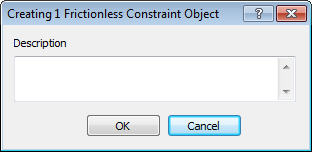
To apply frictionless constraint to a surface of the model, select a surface and then choose the Frictionless tool from the expanded Constraints panel of the Setup tab in the Ribbon of the Autodesk Simulation Mechanical; the Creating Frictionless Constraint Object dialog box will be displayed, refer to figure given below. In the Description exit box of this dialog box, you can enter a comment or description about the frictionless constraint being applied. Next, choose the OK button; the frictionless constraint will be applied to the selected surface.
Creating Frictionless Constraint Object

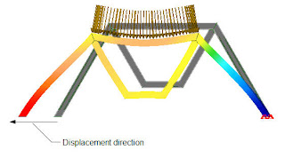
Below Figure A shows the model with frictionless constraint is applied at the bottom planar surface of a structure member in FEA editor environment of Autodesk Simulation Mechanical and Figure B shows the same model in the Result environment of Autodesk Simulation Mechanical after performing the analysis. Note that as the frictionless constraint is applied, the selected surface will not be allowed to deform in its normal direction, refer to Figure B.
Figure - A

Figure - B


Creating mechanism in CATIA V5

Friday, April 26, 2013

Extruding a Sketch in SolidWorks

Adding Parts to a Spec Sheet from a catalog in AutoCAD Plant 3D


You can add parts from a catalog to a newly created spec or an existing spec. For example, to add a pipe of size ranging from 3” to 10”, select the Pipe option from the Part category drop-down list of the Common Filters area in the Catalog Browser in AutoCAD Plant 3D, refer to the below figure.


Next, you need to set the size range of the pipe to be added by using the From and To drop-down lists of the Size range group that will be displayed on choosing the Pipe option from the Part category drop-down list; pipes under the specified range will be displayed in the table. Select the different pipe size from the table and enter the property values (Material, Material Code and Schedule) in the options available in the Property overrides area, refer to below figure. Next, select the Apply property overrides to parts added to spec check box and choose the Add to Spec button; the pipe group will be added to the spec sheet. Similarly, you can add fittings that you want to use when routing a pipe. Also, you can add multiple parts by loading multiple catalogs using the Catalog drop-down list.


Creating Smooth Curve Between Two Existing Sketched Entities in Autodesk Inventor


In Autodesk Inventor, you can create a smooth (G2) continuous curve between two existing curves. The existing curves can be arcs, lines, splines, or projected curves. To create a smooth curve, choose the Bridge Curve tool from the Draw panel of the Sketch tab in the Ribbon of Autodesk Inventor, you will be prompted to select the curves one after the other. Select both the curves; a smooth G2 continuous curve, known as bridge curve, will be created between the selected curves. The profile of the bridge curve depends on the position of the points selected. Below figure shows points of the curves selected for creating smooth curve between them and the resulting curve created.


Wednesday, April 24, 2013

AutoCAD MEP Textbook by Prof. Sham Tickoo and CADCIM Technologies


CADCIM Technologies announces the release of AutoCAD MEP 2014 for Designers textbook by Prof. Sham Tickoo


CADCIM Technologies, a pioneer in the field of CAD/CAM textbooks, announces the release of AutoCAD MEP 2014 for Designers textbook by Prof. Sham Tickoo, Purdue University Calumet, USA and CADCIM Technologies on 20th May, 2013. For detailed information about the textbook and its table of contents, please click on the link given below:

 http://www.cadcim.com/ProductDetails.aspx?ISBN=978-1-936646-57-9

Tuesday, April 23, 2013

Introduction to Effective Mesh in Autodesk Simulation Mechanical

An effective mesh is a mesh that provide you maximum accuracy in less computational time. If the mesh is very fine, the result will be accurate but the time taken to obtain the result will be more. Therefore, it is very important to make proper balance between number of elements in a mesh and computational time taken for analysis. In Autodesk Simulation Mechanical, to make proper balance between number of elements in a mesh and computational time taken for analysis, you can create fine mesh only in the region of high stress and strains by adding the refinement points. Below figure shows the a model with mesh with refinement points added.

Variable Pressure in Autodesk Simulation Mechanical


The variable pressure is applied by specifying different pressure magnitude along a direction of the selected surface at uniform intervals.


Hydrostatic Pressure in Autodesk Simulation Mechanical


Hydrostatic pressure is a pressure that is exerted by a fluid at equilibrium. It varies linearly from the level of the fluid in the direction of increasing depth of the fluid. The magnitude of the hydrostatic pressure is directly proportional to the depth of the fluid and to the density of the fluid.


Remote Load in Autodesk Simulation Mechanical


A remote load is a nodal load or boundary condition that is originated from a point that is located in the space, not on the model. In other words, the load that is originated from a point located in the space, transmitted to the model through line elements such as beam, truss, or similar line elements is called as remote load. You can apply a remote load like you apply a force on the model with the only difference that the location of the remote load origin can be anywhere in the space.


Model Preparation using NX Nastran

Many time before analysis on a model, it is necessary to simplify that. After the simplification, the model become easy to meshing. For preparing model, we can use two type of process; geometry idealization and geometry abstraction.

The geometry idealization is the process to remove or suppress features from the model for proper defining a mesh. You can use the geometry idealization process to remove features such as bosses, fillet,  champhers, that are not significant in analysis.

The geometry abstraction operations can be perform on the geometry within the FEM environment. Using geometry abstraction operation you can remove small fillets as well as the small holes from the model.

Below the figure shows the master part with all its features and the next figure below it shows the prepared part for analysis after removing the small features that are not important for analysis.


Master Part in NX Nastran

The Idealized Part

Creating Midsurface in NX Nastran

You can simplify your geometry for analysis by creating a midsurface. The midsurface tool generate an middle surface between pairs of surfaces selected. After generating the midsurface, you can use it to perform analysis directly and apply uniform shell meshing.

Below the figure shows the master part shown with default thickness, and the next figure shows the part after creating the midsurface.
Master Part

Master Part After Creating Midsurface


Preparing model for Swept Meshing in NX Nastran

In Swept Meshing, the software create 2D (surface) element on one face of the model and then copy that mesh upto the target face. It then generates 3D (solid) elements connecting the two faces.

In case of complex and large model, it become difficult to create swept meshing. In NX Nastran you can use Split Body tool to split the model for preparing swept meshing. In splitting operation you divide the model using the geometry or planes.

For confirming the proper splitting, you can use Check for Sweepable Body check box of this dialog box, to verify whether the part is ready for swept meshing or not. If the model is in  Red color, that indicates you cannot currently generate a swept mesh on the part. For generating a swept mesh, you must split the part further. Yellow color indicates the ambiguity condition. It indicates, you may be able to generate a swept mesh on the part but that the software will show warning about mesh. However, you still need to divide the part further for successfully generate a swept mesh. While the Green color indicates that you are able to generate a swept mesh on the body without further splitting the body.

Below the figure shows the model before splitting and model after splitting operation.
The Model before Spliting                       The Model after Spliting